Click on a property in the image to jump to its description.
Click on a property in the image to jump to its description.
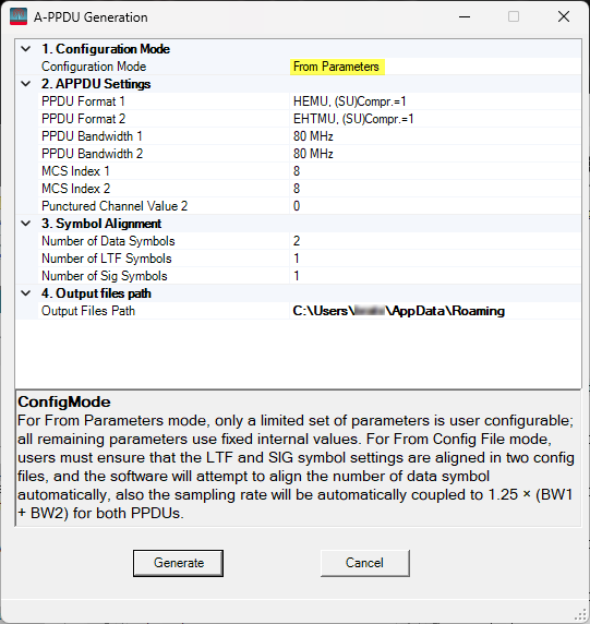
For From Parameters mode, only a limited set of parameters is user configurable; all remaining parameters use fixed internal values.
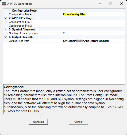
For From Config File mode, users must ensure that the LTF and SIG symbol settings are aligned in two config files, and the software will attempt to align the number of data symbol automatically, also the sampling rate will be automatically coupled to 1.25 x (BW1 + BW2) for both PPDUs.
Select the first PPDU format in a A-PPDU.
Select the second PPDU frmat in a A-PPDU. The selectable range is automatically coupled with APPDU Format.
Options: 80 MHz | 160 MHz.
Options: 80 MHz | 160 MHz.
Select the MCS Index for PPDU 1.
Range: 0 to 13.
Select the MCS Index for PPDU 2.
Range: 0 to 13.
Set the value of punctured channel pattern for non-OFDMA.
For 80 MHz bandwidth the range is 0 to 4.
For 160 MHz bandwidth the range is 0 to 12.
Select the appropriate *.scp configuration file for PPDU 1.
Select the appropriate *.scp configuration file for PPDU 2.
For From Parameters mode, the supported range is 1 to 332.
For From Config File mode, if the user-interface value exceeds the maximum of the two values defined in the configuration files, the user-interface value will remain unchanged and be used; otherwise, it will be automatically adjusted to that maximum value.
Options: 1 | 2 | 4 | 6 | 8.
For HEMU and (SU) Compr.=1 PPDU, the supported range is 1 to 2.
For VHT PPDUs, the value is fixed to 1.
For other PPDU types, the supported range is 1 to 4.
Select the export directory for the generated waveform and configuration files.